Permanent Magnet Motor
This website gives a short overview of electrical machines used as permanent magnet motors and generators, their advantages and some
application fields especially in the high speed domain. Here, a permanent magnet motor is supposed to be a synchronous machine with a
magnetic excitation on the rotor, also known as brushless dc motor, PMSM or BLDC. The difference is, that latter one is typically fed
with a rectangular current form whereas the first one is fed by a sinusoidal current form. The challenges of developing and manufacturing
permanent magnet motors and generators are explained. With e+a located in Switzerland, there is a competent partner with more than 28 years
of experience in designing and producing customized permanent magnet motor elements for various application areas.

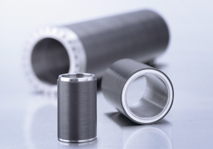
Rotor of a permanent magnet motor with CFRP sleeve
Further interesting operation fields of high speed permanent magnet motors are applications where a standard gearbox is used to translate the rotational speed of conventional power grid frequency (50/60 Hz) driven motors to higher speed levels. A replacement of this gearbox and the related conventional motor with a speed controlled drive consisting of a high speed permanent magnet motor and a rectifier increases the overall efficiency and reduces the maintenance significantly.
The compressor industry is an example, where high efficiency, oil-free operation and no emissions make electric high speed permanent magnet motors the most environmental friendly compressor drives (For compressor applications, also asynchronous machines could be a good alternative due to its robustness). In the context of emission free application energy storage systems with high speed flywheels not only take advantage of high speed permanent magnet generators. Thus fossil generators with unwanted emissions can be avoided and maintenance costs can be reduced significantly. Cryo applications actually experience a very similar revolution of its drive technology. Directly driven motor elements replace a set of a gear box and a 50/60Hz standard motor. Efficiency can be increased, the needed space is by far downsized and maintenance costs are reduced. Hence energy recovery systems e.g. become more and more interesting from a financial and an ecological point of view. Thus permanent magnet motor elements contribute partly to the ongoing development of green energy applications.
e+a in Switzerland offers a wide product portfolio of high speed motors or generators respectively. With more than 28 years of experience and more than 150,000 different high speed induction machines and permanent magnet synchronous machines running, e+a is one of the world leaders in developing and manufacturing highly customized high speed motors. Furthermore, a professional equipped test bench with all the newest inverters and a partial discharge test system allows detailed analysis and adaptation of rectifier and motor and a very well support for system integrators.

Rotor of a permanent magnet motor with CFRP sleeve
Introduction
Various requirements are actually leading to a growing demand for high speed permanent magnet motors and generators. First of all, the continuous need for an increased power density. Due to the quasi linear relation between rotational speed and shaft power of an electrical machine, increasing the rated speed is an effective way to boost power density and efficiency. Hence this approach takes advantage of increasing shaft power without changing the size of the machine. On the other hand, the same performance can be provided in a smaller volume. The latter is paramount in the field of machine tool applications for example. Thus spindles or the machine tool in a whole become smaller, weight is reduced and dynamical behavior is enhanced. Another point in this industry is the cycle time that a machine tool needs to complete a specific operation. The faster a tool can be moved and rotated the faster it is able to complete its task, not taking into account that high speed cutting operation rely on top speed to machine time efficiently respective parts.Further interesting operation fields of high speed permanent magnet motors are applications where a standard gearbox is used to translate the rotational speed of conventional power grid frequency (50/60 Hz) driven motors to higher speed levels. A replacement of this gearbox and the related conventional motor with a speed controlled drive consisting of a high speed permanent magnet motor and a rectifier increases the overall efficiency and reduces the maintenance significantly.
The compressor industry is an example, where high efficiency, oil-free operation and no emissions make electric high speed permanent magnet motors the most environmental friendly compressor drives (For compressor applications, also asynchronous machines could be a good alternative due to its robustness). In the context of emission free application energy storage systems with high speed flywheels not only take advantage of high speed permanent magnet generators. Thus fossil generators with unwanted emissions can be avoided and maintenance costs can be reduced significantly. Cryo applications actually experience a very similar revolution of its drive technology. Directly driven motor elements replace a set of a gear box and a 50/60Hz standard motor. Efficiency can be increased, the needed space is by far downsized and maintenance costs are reduced. Hence energy recovery systems e.g. become more and more interesting from a financial and an ecological point of view. Thus permanent magnet motor elements contribute partly to the ongoing development of green energy applications.
Challenges
The mentioned advantage of high speed permanent magnet motors and generators can only be achieved by using high quality motor elements. The reason for that is that due to the high rotational speeds, the centrifugal forces on the rotating motor part (rotor) can be very high leading the materials to the edge of mechanical stress resistivity. Failures in motor elements can result in crashes affecting the environment or at least damage the system, where the generator or motor is built in. To prevent this, various physical aspects need to be calculated in a challenging development process, taking electromagnetic, thermal, mechanical stress and structure dynamic aspects into account. The applied computational methods need to be combined with a long experience, to extend actual operation limitations with keeping safety in mind as highest priority. Furthermore, the interaction of the rectifier and the permanent magnet motor needs to be known, because the rectifier has a deep impact on heating, noise, clogging, and efficiency of the motor. Especially the interaction of various converter systems with a high speed motor element demands very specific knowledge and experience. Hence tests of above described applications are crucial to succeed. They require an intense relation between the power electronic and high speed permanent magnet motor specialists. Furthermore the infrastructure enabling performance tests are highly complex and usually not available on the market. Very often the related costs exceed by far the costs incurred during the whole development process of a new motor element product line.Inverter
Typical inverters are working on base of the pulse wide modulation method, where a continuous switching of voltage or current controls the output waveform. Due to the need for faster high speed permanent magnet motors, the switching frequency increases as well (in modern inverters, IGBT's are used). Although noise and efficiency improve as the number of pulses increase, the inverter leads also to a few drawbacks, especially because of fast switching transients which can be understood as a significant source of stray losses. Additional time harmonics caused by a switching mode inverter has a negative impact on the air gap flux distribution. These harmonics cause additional eddy current losses in the motor elements especially in the rotor, which lead to higher temperatures and a possible degrade of the mechanical behavior. The switching frequency has another impact on the high speed permanent magnet motor, namely on the insulation, which is severely stressed by the repetition and the steepness of the pulse wave front. When IGBTs are used, the high rate of voltage rise of typically 0 - 650 V in less than 0.1 Ás leads to approximately 10,000 V/Ás. This fact results in adverse effects on the motor insulation. These steep rising and falling pulses lead to an uneven distribution of voltages within the motor, especially during switching transitions. Without a deep knowledge of the permanent magnet motor insulation system and the inverter itself an insulation deterioration and subsequent failure of the motor can occur. In this context partial discharge effects and rotor over heating are well known failure sources. The latter can lead to an unwanted carbon fiber burst due to thermal or mechanical stress in the respective resin carbon fiber compound (synchronous machines).Conclusion
Permanent magnet motors and generators offer several advantages like decreased installation space for higher power and unnecessary gearboxes. These advantages apply for several fields and are intensively used in the machine tool, compressor, cryo and energy generating industry for example. Designing and producing these high speed permanent magnet motors and generators is an exciting task, where the usage of most modern computational methods for the development process is as important as a wide range of experience and expertise to extend actual operation limitations in a safe way. Not only is the knowledge of high speed permanent magnet motors necessary but also a deep inside in inverter technology, partial discharge phenomenon and so called stray or additional loss.e+a in Switzerland offers a wide product portfolio of high speed motors or generators respectively. With more than 28 years of experience and more than 150,000 different high speed induction machines and permanent magnet synchronous machines running, e+a is one of the world leaders in developing and manufacturing highly customized high speed motors. Furthermore, a professional equipped test bench with all the newest inverters and a partial discharge test system allows detailed analysis and adaptation of rectifier and motor and a very well support for system integrators.